Well hear we go, the first draft of my how to guide.
Firstly thanks to the people behind the CamelCC and my-gti.com guides, without them this would have been a lot more difficult.


There are still some more / better pictures to be added but this should start to give you an idea of what's involved in the installation. If you have any questions about the install please post them in the thread or if you want some help sourcing the parts or completing the phyiscal install then drop me a PM
 What does it do:
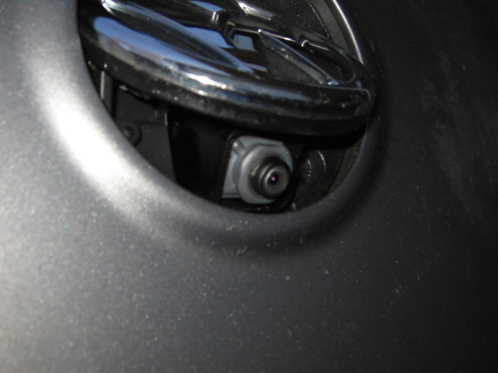
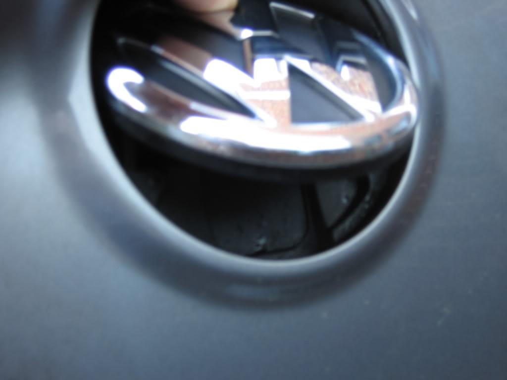
Here's a couple of pic's of the badge/camera
Camera activated: -
Normal mode with camera hidden: -
And a short video of it in action (sorry for the rubbish quality but you get the idea)
Parts Required:5K0 827 469R ULM - New rear badge with internal camera (@ £243.80)
5M1 970 161AC - Cable between badge and RNS510 (@ £44.85)
3B0 972 722 - 4 pin connector for camera (@ £2.99)
4B0 973 712 - 4 pin controller for badge (@ £2.76)
1J0 973 802 - 2 pin connector to interface with old badge wiring (@ £1.50)
1J0 972 923 - 2 pin connector (Reverse Signal Feed) * (@ £0.87)
1J0 972 712 - 2 pin connector (Reverse Signal Feed) * (@ £2.19)
000 979 131 - Repair wire (4 required) (@ £1.75 each)
000 979 132 - Repair wire (1 required) (@ £1.30)
000 979 133 - Repair wire (1 required) * (@ £1.75)
000 979 129 - Repair wire (1 required) * (@ £1.75)
3C8 827 861A - Drain Tube (@ £1.65)
000 979 950 – Webbing Adhesive (10M) (@ £4.50)
* Optional Parts to save scotch locking a wire into the reverse 12v positive wire.
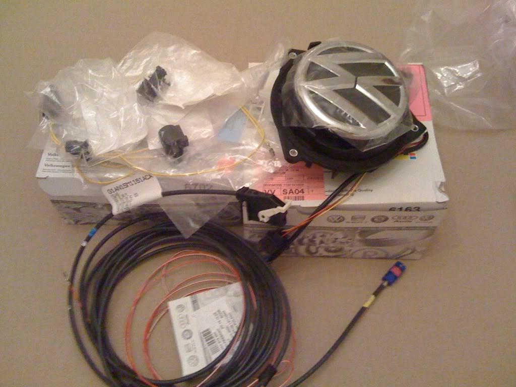
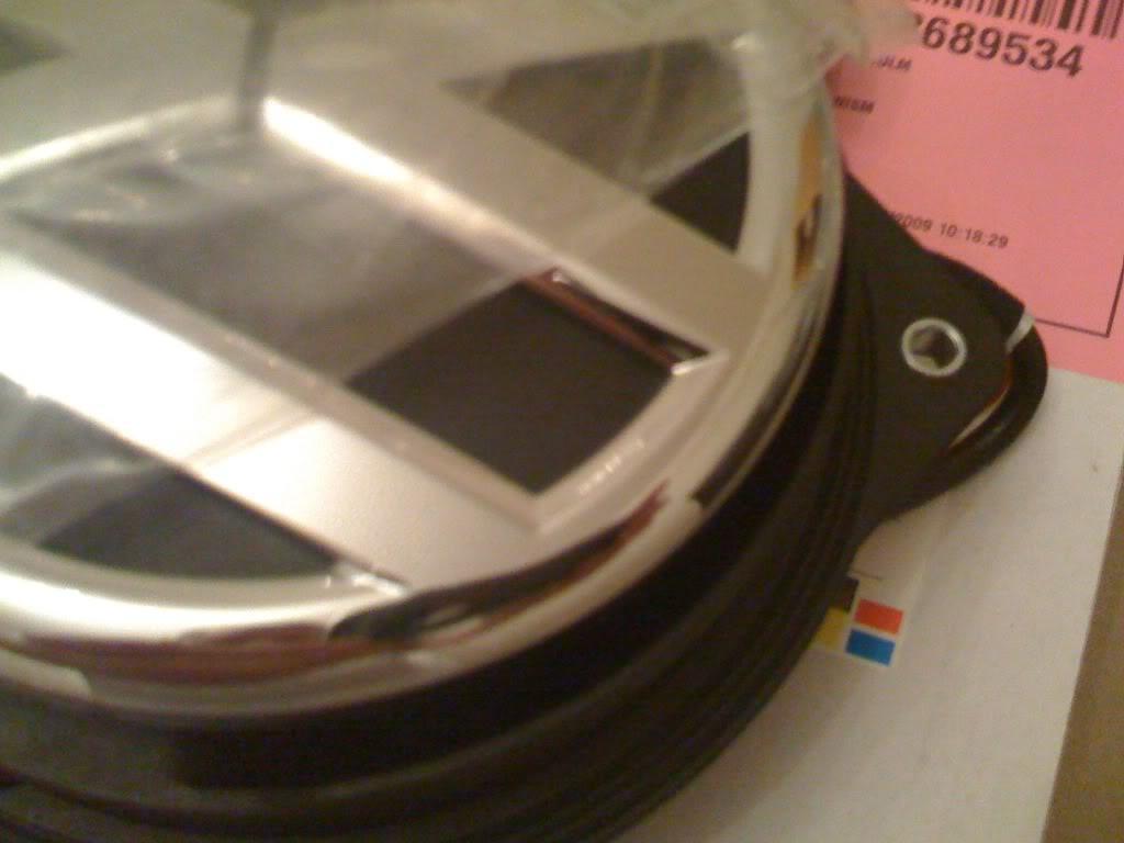
This will include the newer style bevelled edge on the rear VW badge: -
Other bits and bob
5 amp cable (abot 2 meters)
5 amp mini fuse
Either Piggy Back Fuse holder (
click) or Buy 1 x 000 979 021 from VW and add a new fuse to the fuse box.
Heatshrink
Electrical Insulation Tape
Tools Needed: -T20 & T25 Torx's Screw Drivers
Phillips Screw Driver
Trim Removal Tools (Like the Bojo's Set)
Soldering Iron
Stanley Knife
Wire Cutters
Tape Measure
10mm Socket
13mm Deep Socket or Spanner
Junior Hacksaw
Small Angle Grinder or Dremel with Metal Cutting Blade
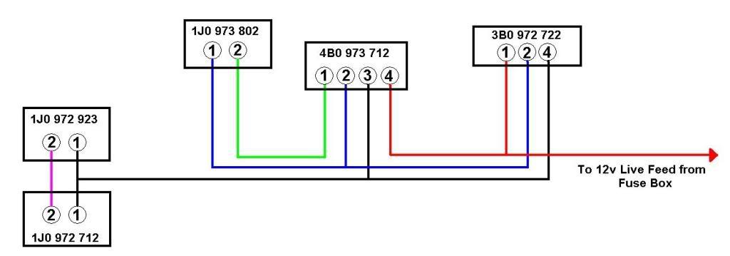
Step 1 - Creating the LoomHere's a very basic wiring diagram to show where everything goes: -
Here's an overview showing the approx lengths of each of the runs between connections: -
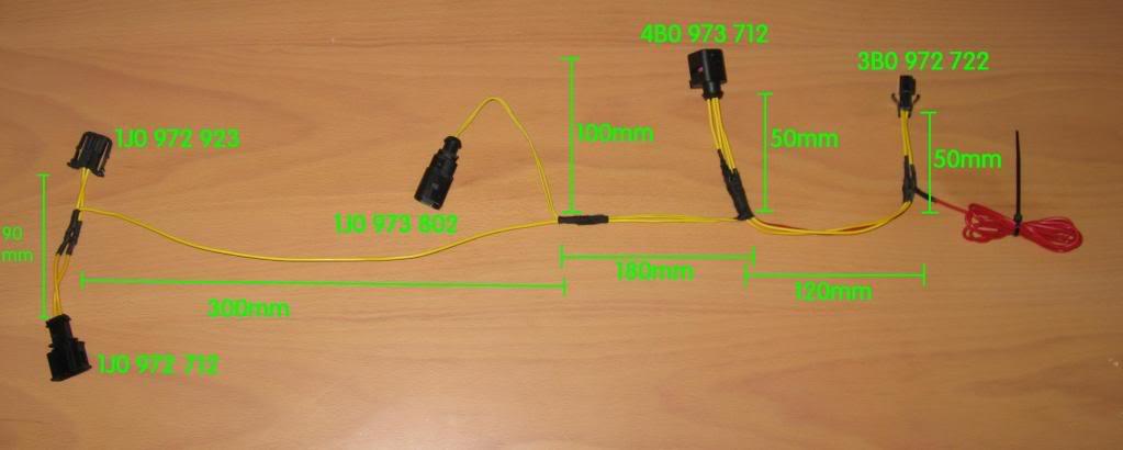
The red 12v live feed wire I added around 700mm to this and then cut down when connecting it to the cable being run from the fuse box.
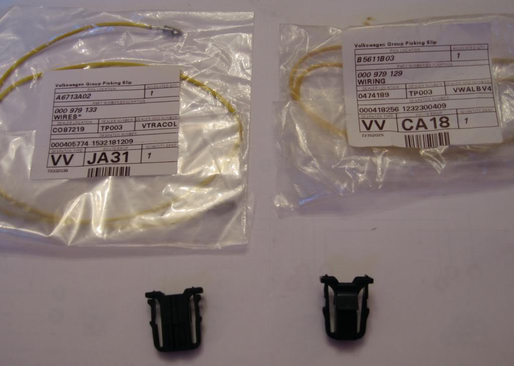
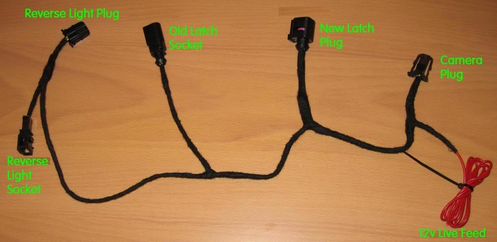
Connectors 1J0 972 923 & 1J0 972 212 and the repair wires 000 979 133 & 000 979 129 for the reverse signal pick-up: -
Connector 1J0 973 802 and repair wire 000 979 132 for the pick-up of the original latch connections: -
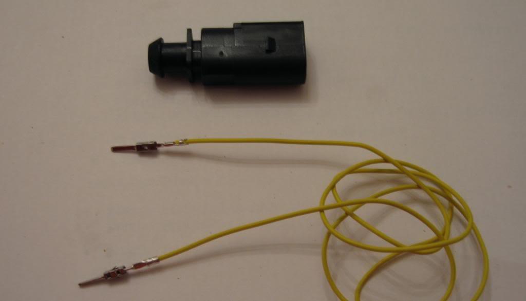
With this connector remember to move the purple plastic prongs in the direction shown to lock off the wires into place: -
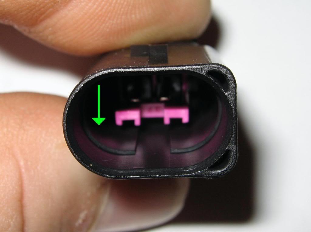
Connector 4B0 973 712 and repair wires 000 979 131 for connection to the latch connections on the new camera badge unit: -
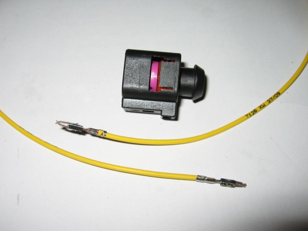
Again the purple plastic needs to be moved in the direction shown to lock off the wires: -
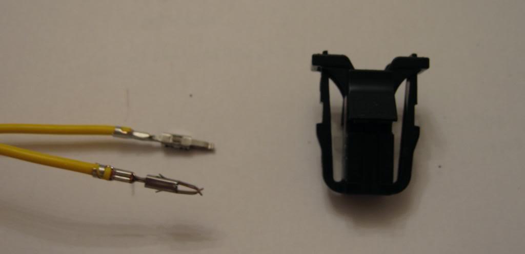
Connector 3B0 972 722 and repair wire 000 979 131 for connection to the camera power side of the new camera badge: -
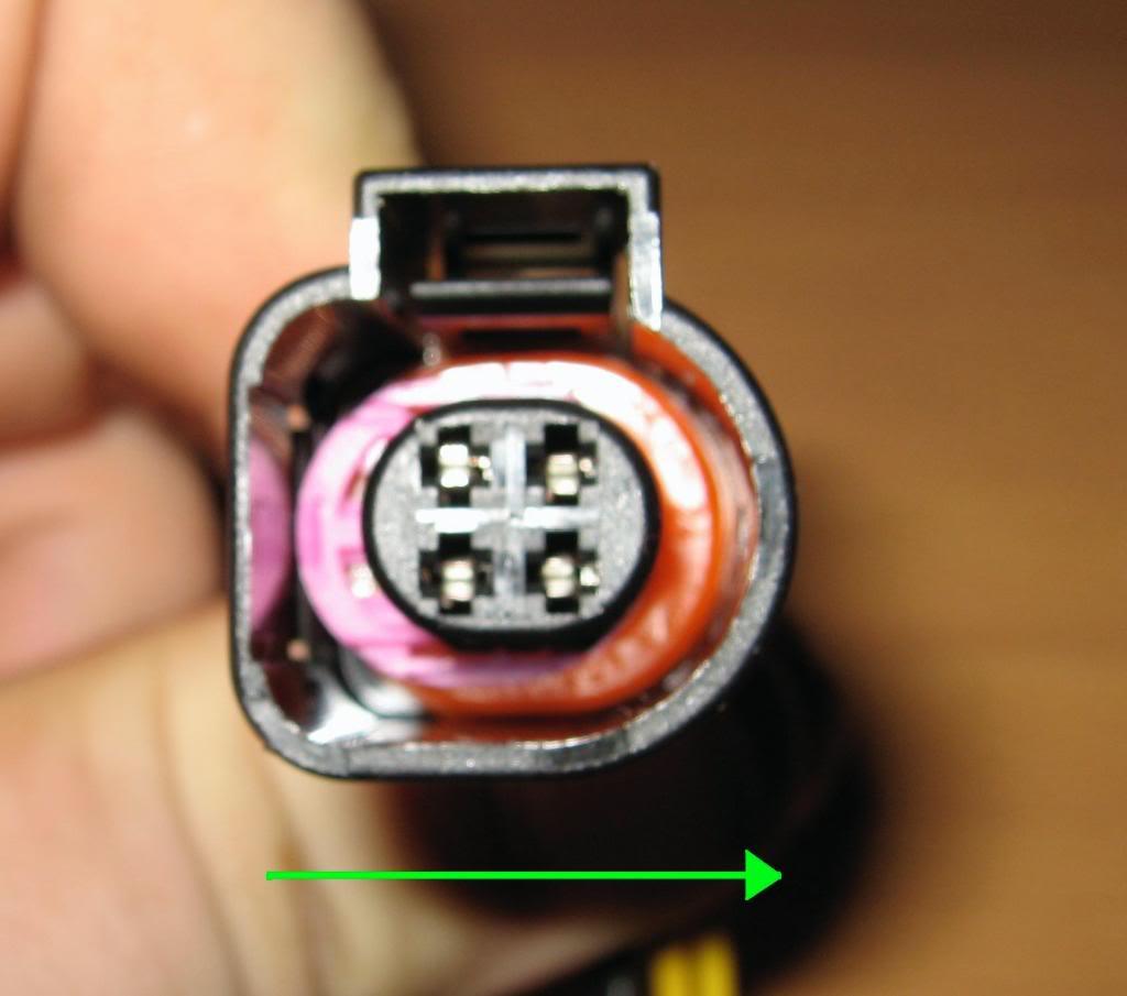
Once the cable has been made up I would recommend testing it with a multi meter first. Then it can be wrapped with the OEM webbing, and here is the finished article.
 Step 2 - Connecting the Coax Cable to RNS-510
Pop off the top vent cover using a trim tool
Towards the back of the vent unit remove the single T20 screw.
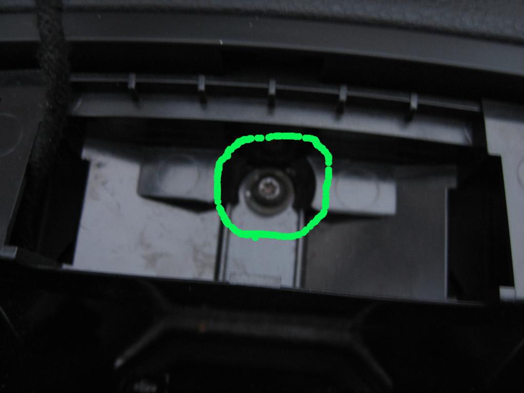
Again using the trim tool lift out the inner vent.
Now remove the two T20 screws holding the rest of the plastic surround in place
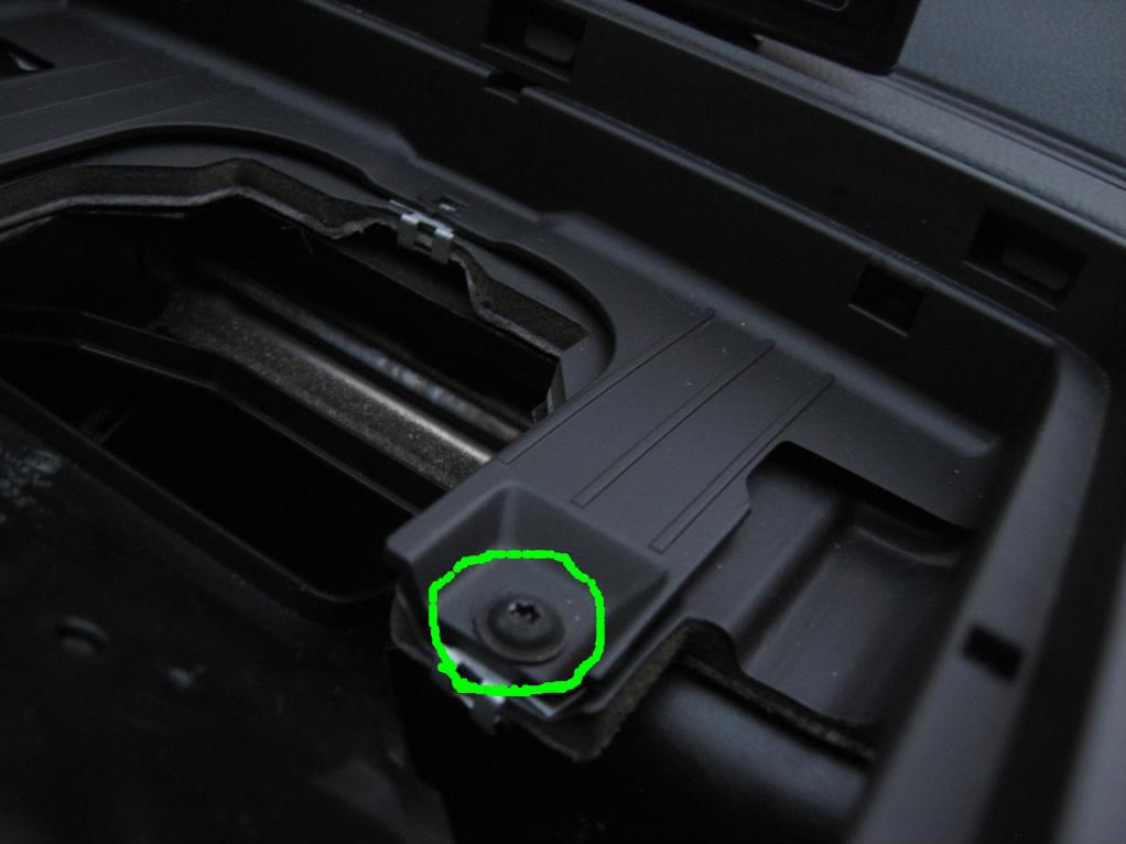
Lift out the top part of the plastic surround with the trim tool.
Now gently prize the upper and lower trim sections apart with the trim tool and lift away the whole section.
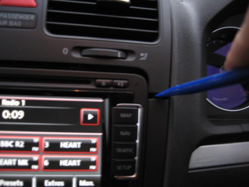
Now remove the two T20 screws hold the top corners of the lower trim piece in place.
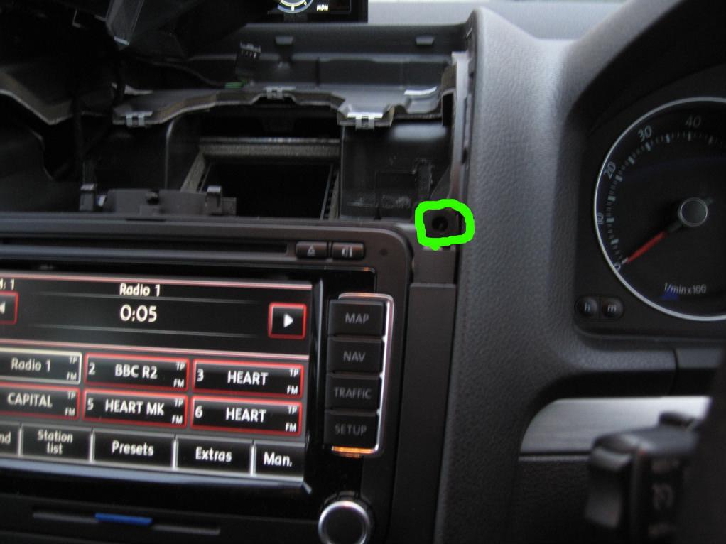
Now working from the bottom upwards gently lift out the lower trim with the trim tool.
Then remove the 4 T20 screws holding the RNS510 in place.
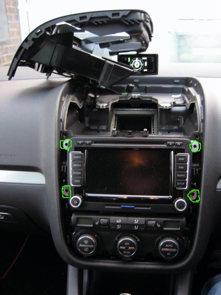
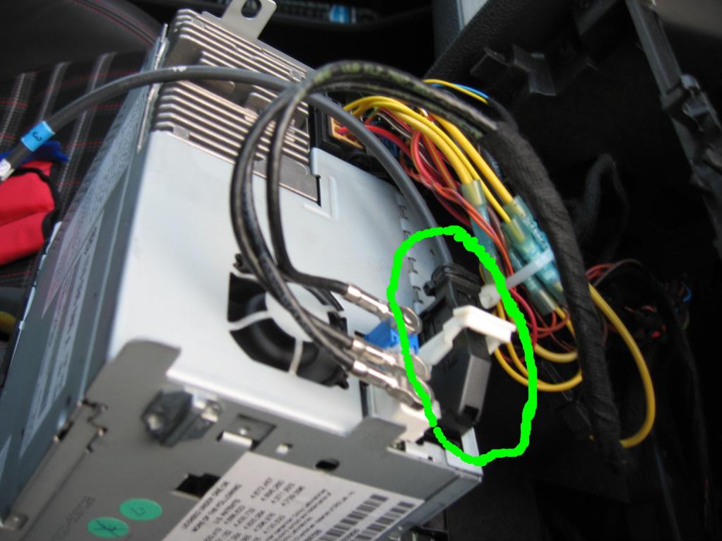
Now connect the long coax cable to the back of the RNS
Remove the steering wheel all the way inwards and downwards and pop off the trim piece in between the steering wheel and clocks.
Now remove the two T20 screws holding the clocks in place (locations shown below). Now move the steering wheel all the way outwards and gently slide the clocks out.
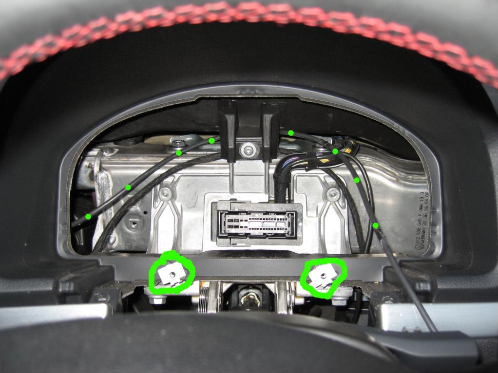
The Coax cable can now be feed through from the RNS, up behind the clock connector and out to the fuse box (shown with the dotted line).
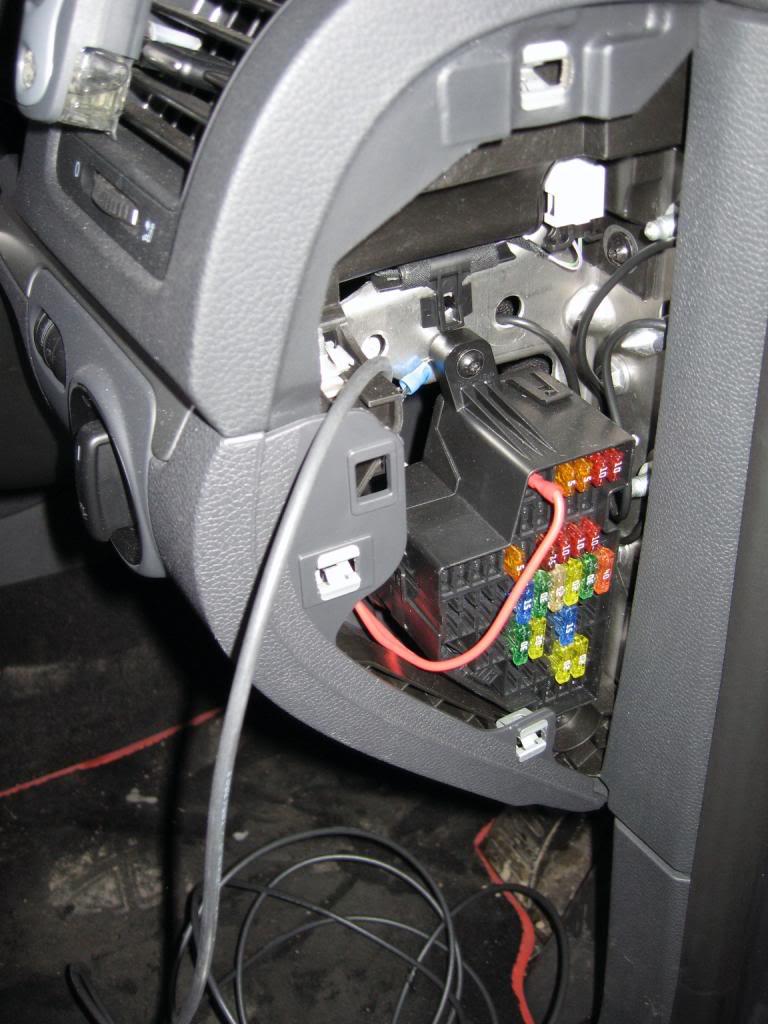
Now refit the clocks, RNS and trim/vent in reverse order of above.
Step 3 - Connecting the 12v perm liveTo do, fuse box guide for adding a new circuit.Step 4 - Running the Coax and 12v perm live Cables to the rearPrepare to run the two cables to the rear of the car by lifting the sill trim(s) with a trim removal tool.
Now remove the right hand plastic covering to the side of the rear seats, if you drop down the rear bench you will find a small panel behind it is two T20 screws, remove these and then the panel will pop off. (best to have a magnetic screw driver for these).
Now release the right hand parcel shelf support, this is attached by one screws under the joint between the lower edge of the support and top of the inside edge of the boot trim (just inside the boot by the seal). The support can now be pulled away, it is attached with three white threaded stud which take a reasonable amount of force to shift.
Next is the C pillar trim, first remove the long central trim at the top of the boot opening, this will reveal a 10mm plastic nut, remove this. Now pop out the airbag plastic label from the other side of the c pillar trim and remove the T20 screw behind it. The C pillar trim can now be popped off, again this will require reasonable force with the trim tools.
You can now run the two cables up to the rear of the car. Make sure these are securely fastened along the way up to the rear and are kept clear of the seat belt mechanism.
I feed the cables out and behind the brace at the back of the C pillar
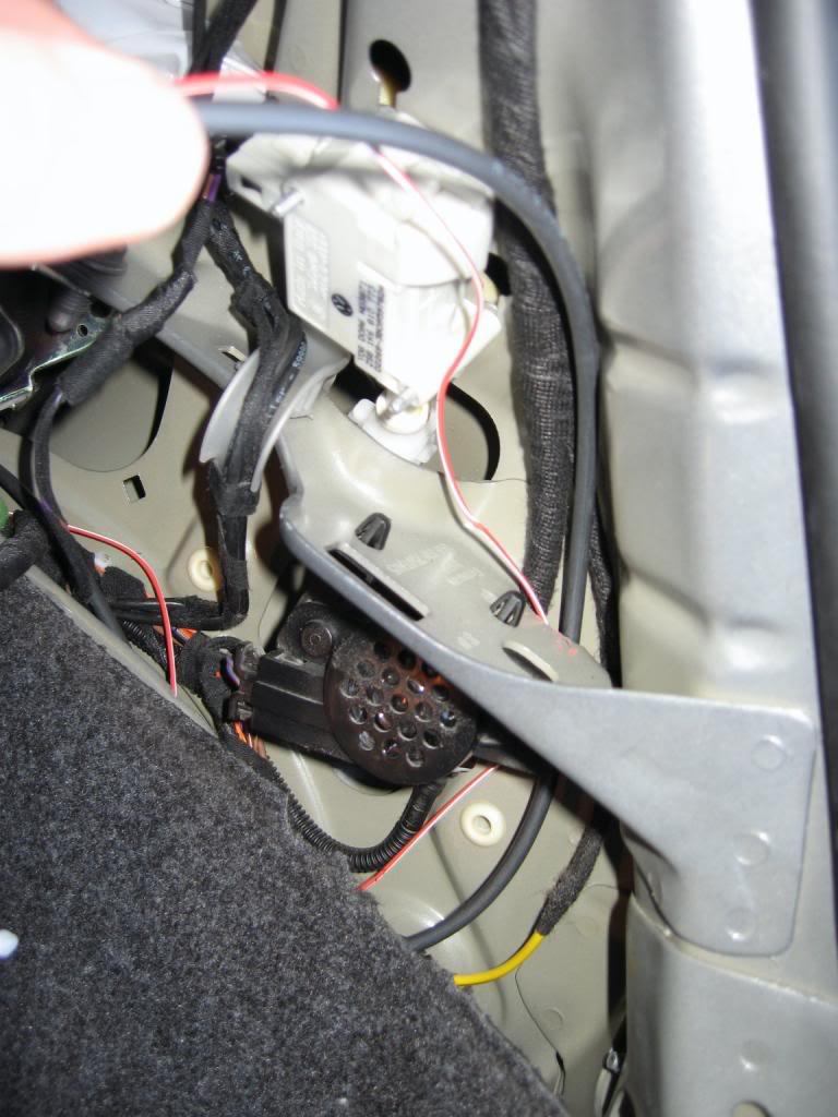 Step 5 - Boot Lid Trim Removal
Now remove the lower boot lid trim by firstly taking out the two slightly hidden phillips screws for the handles
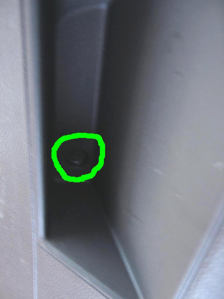
Now with a trim removal trim work you way along the bottom of the trim "popping" it off, again it will take some reasonable force as it uses some metal spring clips. Once it has been removed pop off the upper window trim, this should take far less force.
Step 6 - Removal of rear wiper and existing BadgeTo remove the rear wiper from the outside pop off the plastic cap from the end of the wiper arm and remove the 13mm nut, the wiper arm should now pull off. Then from inside disconnect the washer fluid feed and electrical connector, next remove the 3 x 10mm bolts holding the wiper mechanism in place. It may take some wiggling to free the wiper mechanism but it will eventually come free.
Next remove the electrical connection and three screws holding the rear badge in place
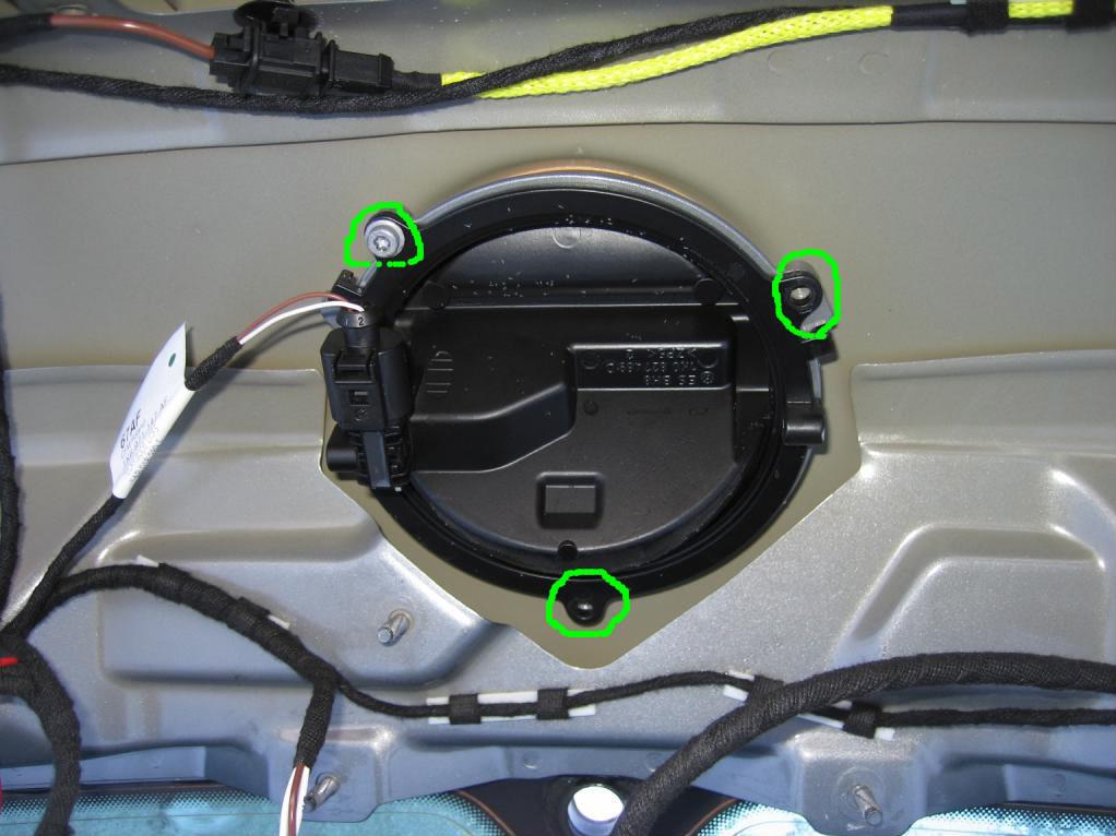
The badge will now twist right and can be puled out.
Now the metal work needs to be trimmed the measurements for the cuts are 60mm horizontal and 55mm vertical.
Before cutting it's adviseable to pop out the electrical wires that are clipped in place near where you will be cutting.
Here is a very rough outline for the cut: -
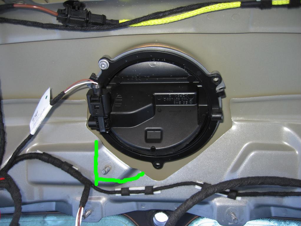
Once cut grind back the sharp edges and cover the bare metal with some primer or a touch-up pen.
Step 7 - Feeding the cables and connecting the new Now release the rubber channel between the boot lid and inner roof line, then feed the two cables up through hole in the inner roof line
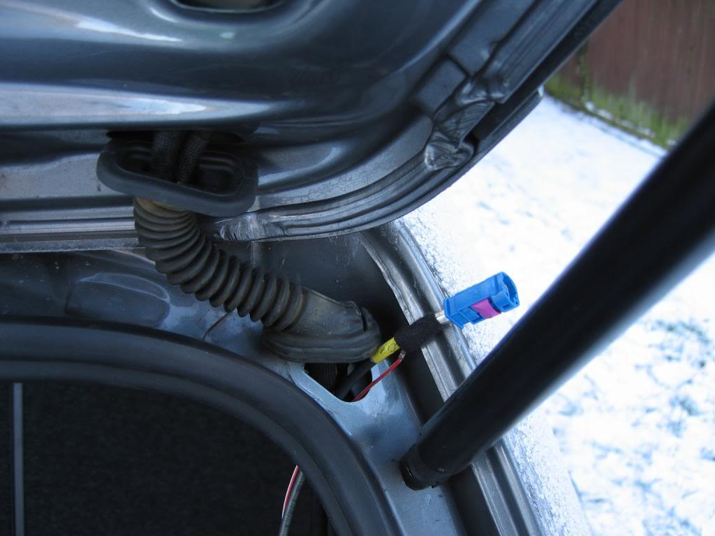
Remove the blue plastic cover from the end of the coax cable
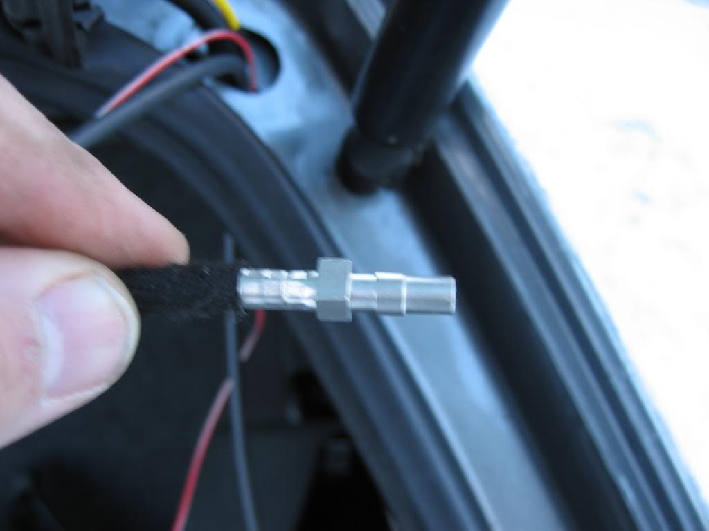
Now feed the two cables through the rubber channel, i found compressing the channel ends together and pulling the cables through using a wire coat hangers was the easiest way.
Then feed cables through the outer hole of the boot lid
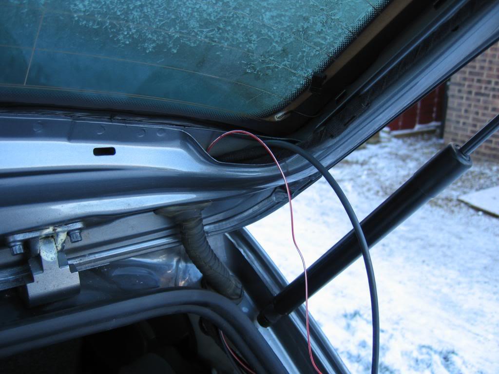
Re-install the plastic cover on the coax cable
Now connect the pre-made loom starting from the left hand side by connecting the reverse signal pick-up and secure the wires in place up to the left hand side of the new badge camera unit
Now install the new badge by twisting it into place and securing it with the three screws removed from the original badge.
Then attach the remaining three connections plug in connections on the new loom (start from the left the original badge signal pick-up (1), new badge lock connection (2) and camera power connector (3)).
Next connect the blue coax cable onto the right hand side of the badge (4) and connect the 12v live feed wire into the new loom.
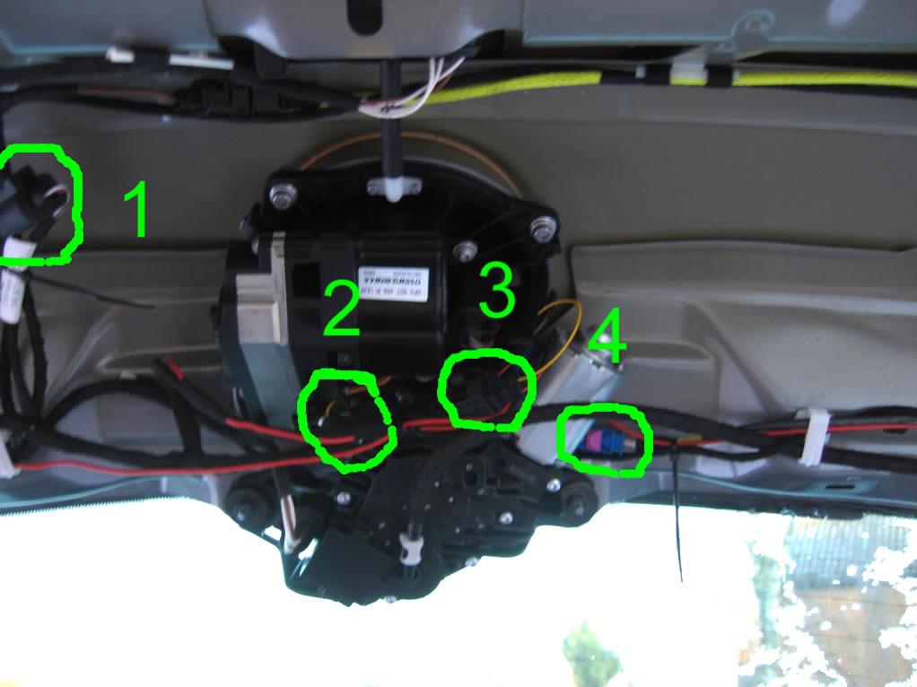
Finally connect the drain tube to outlet on the bottom of the new badge.
Step 8 - Re-installing the rear wiper To be able to re-install the rear wiper one of the support arms has to be removed, this is the left hand lower arm.
My initial cut wasn't enough but the picture below shows the area to complete the cut
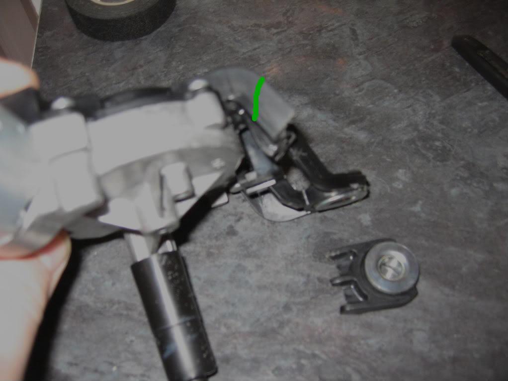
The rear wiper works fine when installed with the two arms.
Step 9 - Coding the RNS-510 & TestingOpen the Navigation (37) controller and select coding, then long coding helper, then in the forth block set bit 6 to on (shown as "Backup Camera Low"), close the long coding and saving the new coding. Reboot the RNS-510 by pressing the "<" & ">" & "i" button.
If not already connected, attach the 12v permanent feed into the fuse box.
Select reverse and as if by magic the image should appear on the screen

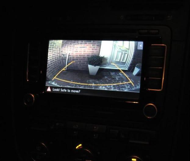 Step 10 - Finishing up
Re-install the boot lid, Rear Windows Trim, C pillar cover, parcel shelf support and sill trims, making sure all cables are secured and won't get trapped in any of the trim clips.
RVC Install........................................Done
