Make a donation

Author Topic: DIY: 2.0T FSI Timing Belt Replacement  (Read 104772 times)

Offline dazza

  • Admin
  • Just look at my post count
  • *
  • Thank You
  • -Given: 90
  • -Receive: 190
  • Posts: 2134
  • Coding Boffin
    • Email
  • My Ride: https://www.mk5golfgti.co.uk/forum/index.php?PHPSESSID=gmlgq3c7lt82nt3rf9s010mjgo&/topic,90967.msg917089.html#msg917089
DIY: 2.0T FSI Timing Belt Replacement
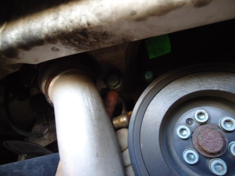
« on: September 09, 2017, 10:04:29 pm »
Ive copied this from http://www.golfmkv.com/forums/showthread.php?t=135872
Its was what i followed when i did my cambelt. Noticed the images are missing so thought i would copy it here and scrape the images.

This is not my work but i found it a great help and it would be a shame to loose such a great resource. :notworthy:  :notworthy:

Figured I'd throw together a little how-to for us with transverse mounted engines to let peeps know more of what's in store to get the job done. Having the engine mounted sideways makes it a little more difficult. If I had to do it again I'd start on Saturday instead of Sunday to not be so rushed. If you don't strip a bolt plan on it taking about 8 hours the first time ...maybe 4-5 hours second time around.

ECS Tuning and DBC Performance offer relatively complete timing belt kits online. I'd get a kit that includes the timing belt, tensioner, both idlers, A/C belt, and coolant. If the kit does not come with the 6 crank pulley bolts and 4 engine mount bolts, you may want add those to your order. They are one time use stretch bolts.

I stole a few pics from the Audizine DIY since the front of their engines is more viewable. More pics later. PM me if you notice any mistakes or want to make a suggest to improve this DIY.

Tools Needed:
Basic socket set
Breaker Bar
T20, T30 Torx bits
6mm, 8mm Allen bits
Pliers
Flathead Screwdriver
5/8" wrench
Torque wrench
19mm 12pt socket

1) Before jacking up the car make sure to loosen the passenger wheel lug bolts.
2) Remove passenger wheel.
3) Unplug MAF sensor and remove factory air box/engine cover.
4) Remove factory "noise pipe" if equipped (quick release at each end, 1 8mm screw, 1 T30 Torx screw).
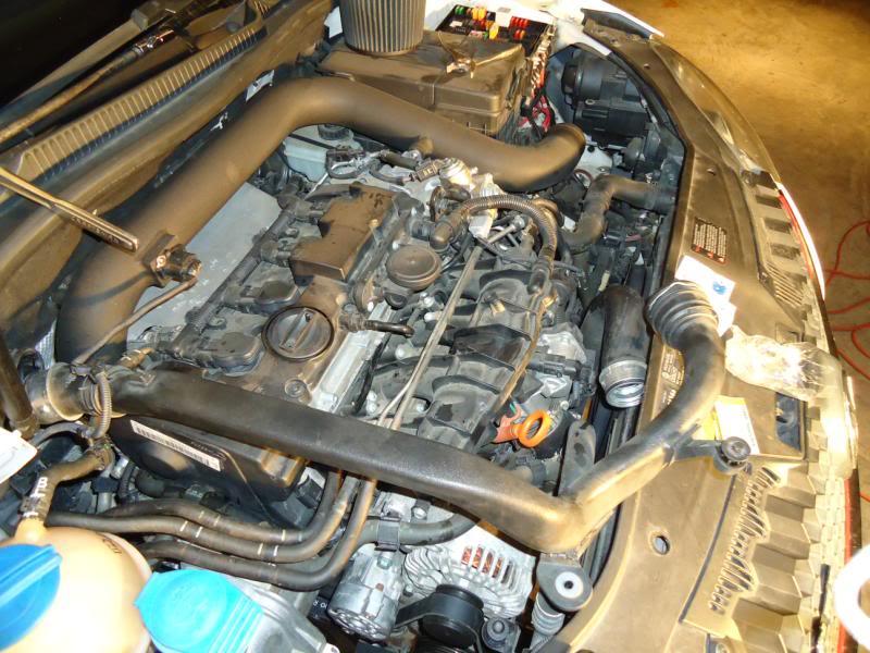


5) Disconnect washer tank from bracket and push to side (1 10mm screw).
6) Disconnect coolant reservoir and push to side. Unplug connector, disconnect small upper hose near cap, and remove screws holding rear of tank (2 T20 Torx screws).
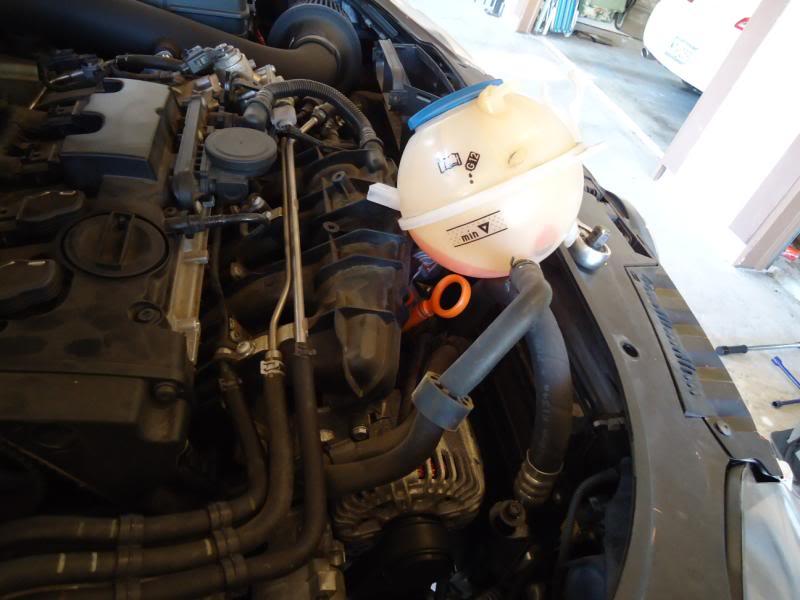


7) Remove black washer bottle support bracket (2 13mm bolts)
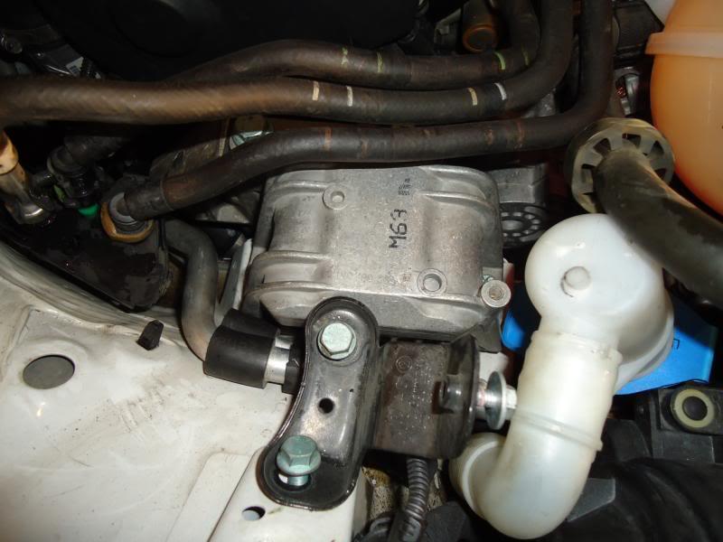


8) Disconnect coolant hose and push to rear of engine bay. Hose passes in front of belt cover.
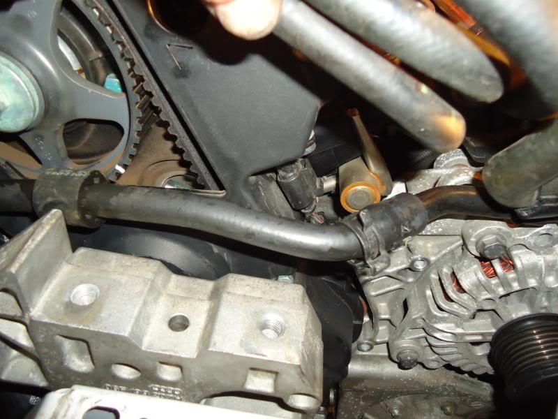


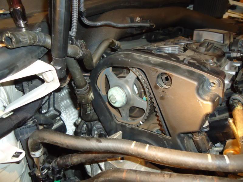
9) Unlock and remove cam sprocket cover using flathead screwdriver.
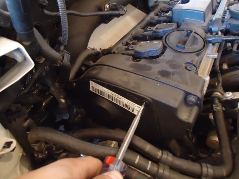


10) Remove under engine plastic dust guard (8 T20 Torx screws)

11) Remove passenger side front lower wheel well liner (7 T20 Torx screws).
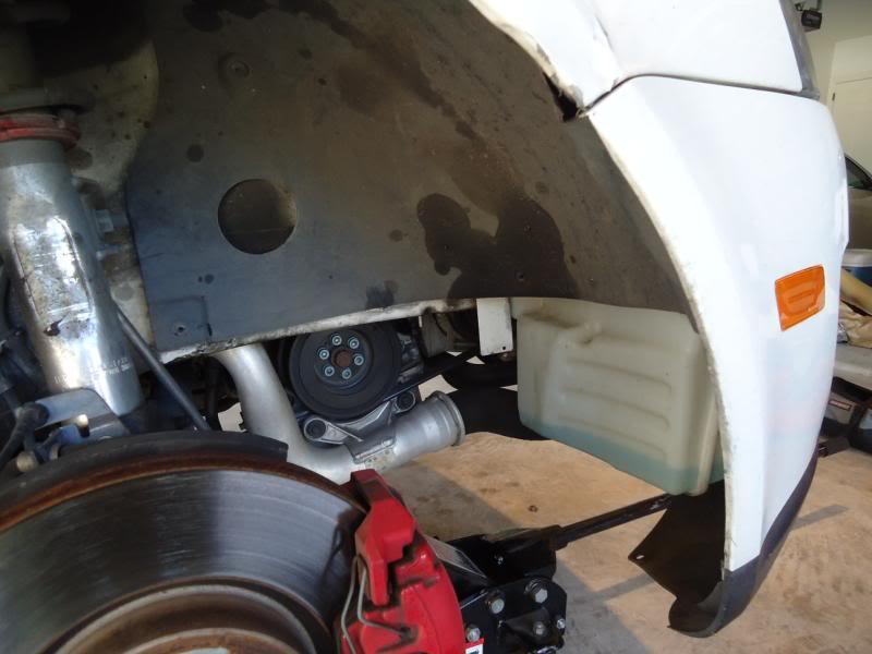


12) Disengage ribbed belt tensioner using open-ended wrench and nail. Remove ribbed belt.
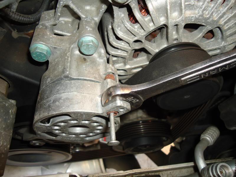


13) Remove ribbed belt tensioner (3 13mm bolts)
14) Remove crankshaft pulley (6 6mm Allen bolts). Have one person hold crankshaft center bolt stationary while another loosens the hex bolts. Be VERY careful not to strip or you may have to drill one out (Don't ask how I know). These are stretch bolts and should be replaced with new bolts upon reassembly.
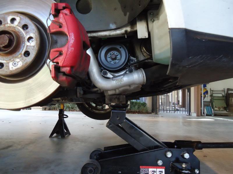
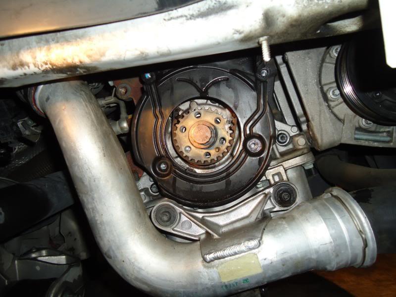


15) Remove black lower timing belt guard (4 10mm bolts)
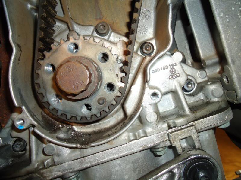


17) Turning clockwise, bring camshaft gear to marking for TDC cylinder 1 by turning crankshaft center bolt (1 19mm 12pt). Marking on camshaft gear must align with arrow on timing belt guard.
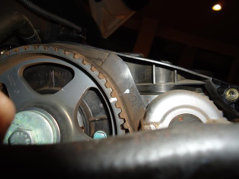


18) Mark bottom sprocket with paint or white out. In case the sprocket is bumped or accidentally spins you will need to have it marked.
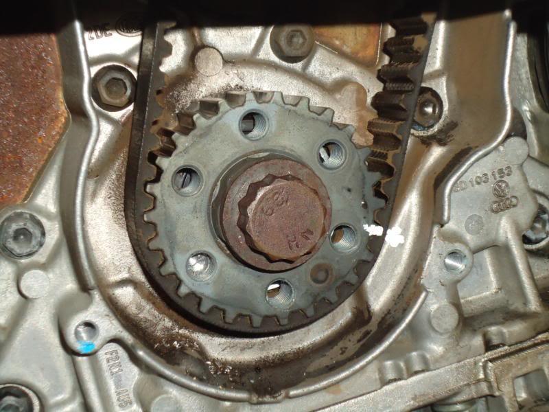


19) Support passenger side of engine using jack or engine lift.
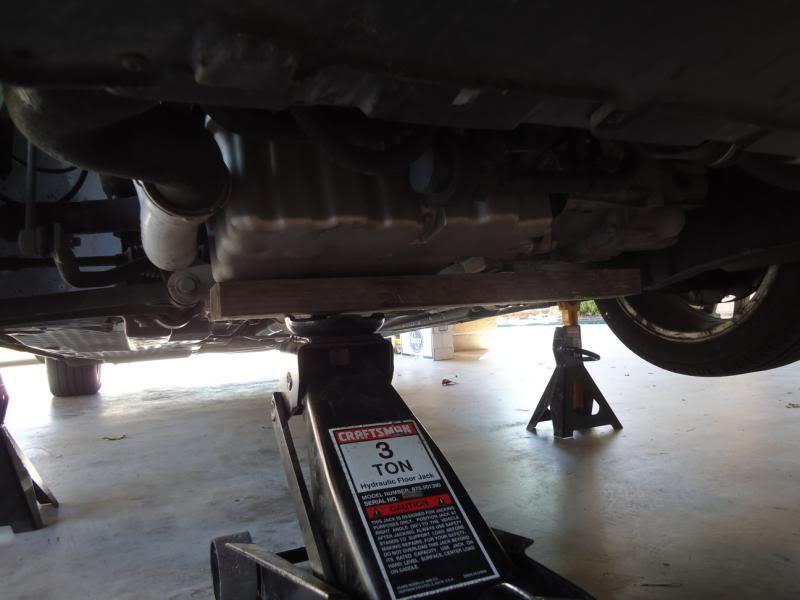


20) Remove side engine mount. Remove the larger bolts first (2 18mm) which connect the mount to the engine followed by removing the smaller bolts (2 16mm) that connect the mount to the car. All 4 of the mount bolts are stretch bolts and should be replaced with new bolts upon reassembly. This may or may not apply if you are using aftermarket mounts and hardware.
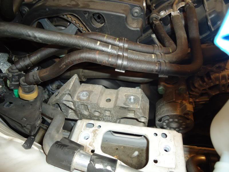


21) Remove lower bolt from engine bracket (16mm bolt).
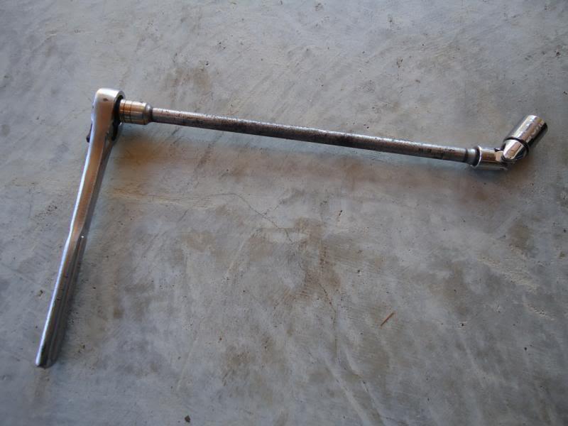


22) Raise engine to gain access to upper engine bracket bolts.
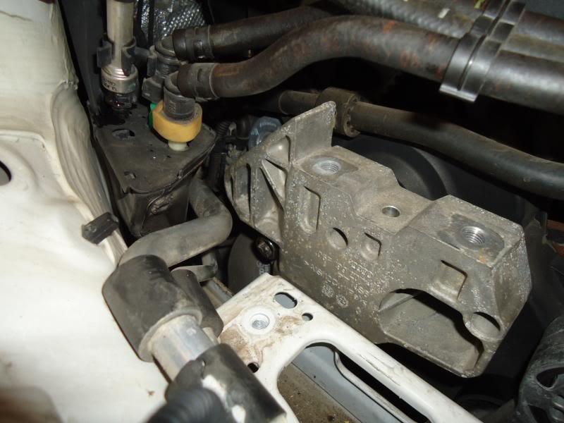


23) Remove upper engine bracket bolts (2 16mm bolts).
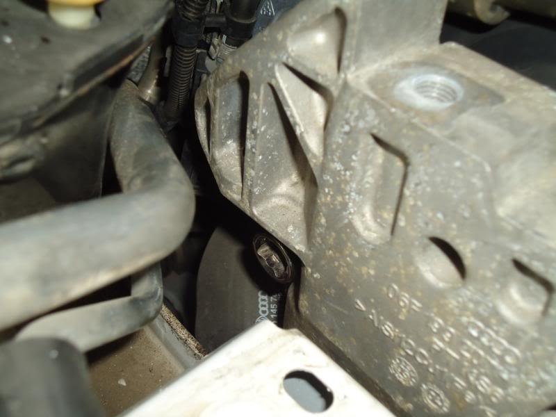


24) Work engine bracket up and out of engine bay. Contrary to what the Bentley manual says, it is not necessary to disconnect the lower engine mount, axles, and downpipe to get the bracket out. Fuel lines do not need to be disconnected either. Bracket will squeeze between fuel lines and plastic timing belt cover.
25) Remove plastic timing belt cover (7 total; 2 T30 Torx, 5 10mm bolts).
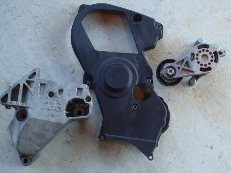


26) Loosen and remove timing belt tensioner (1 13mm nut, 1 8mm Allen). Loosen main 13mm nut then use rotate 8mm Allen bit counter-clockwise to loosen tensioner.
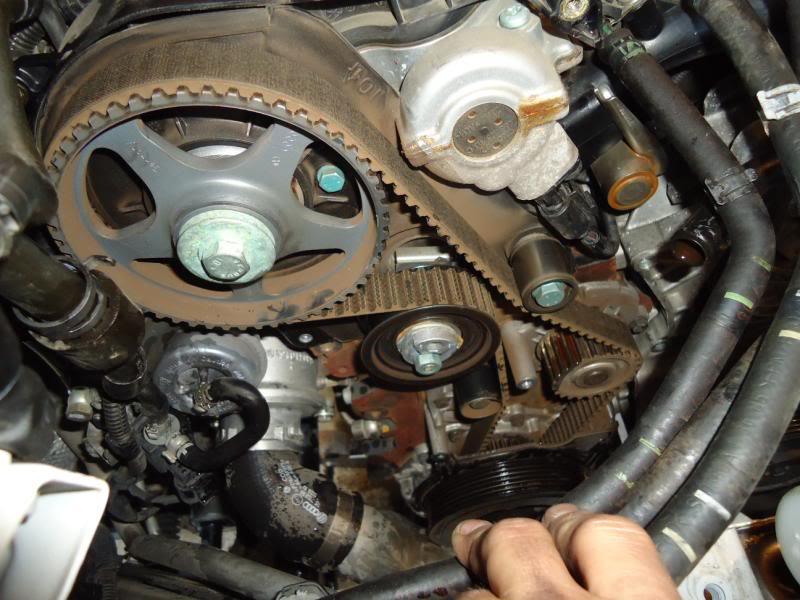


27) Remove timing belt tensioner, timing belt, both idlers
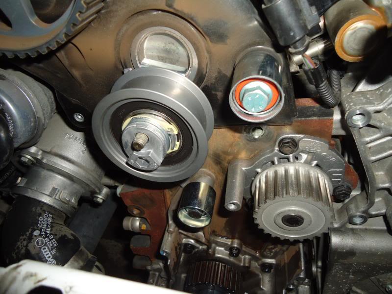


28) If replacing water pump, do so now. Drain coolant from lower passenger radiator hose and from coolant hose going to oil cooler. The oil cooler hose is directly behind the larger radiator fan. Remove and replace water pump (3 10mm bolts). Water pump bolts are 15nm.
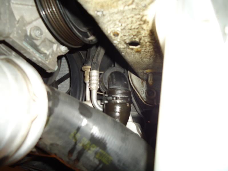
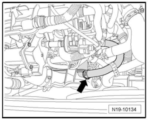


29) Replace idlers. Upper idler is 25nm and lower idler is 35nm
30) Replace timing belt tensioner and timing belt. See my "***TIPS TO PUTTING ON BELT" below at bottom of DIY.
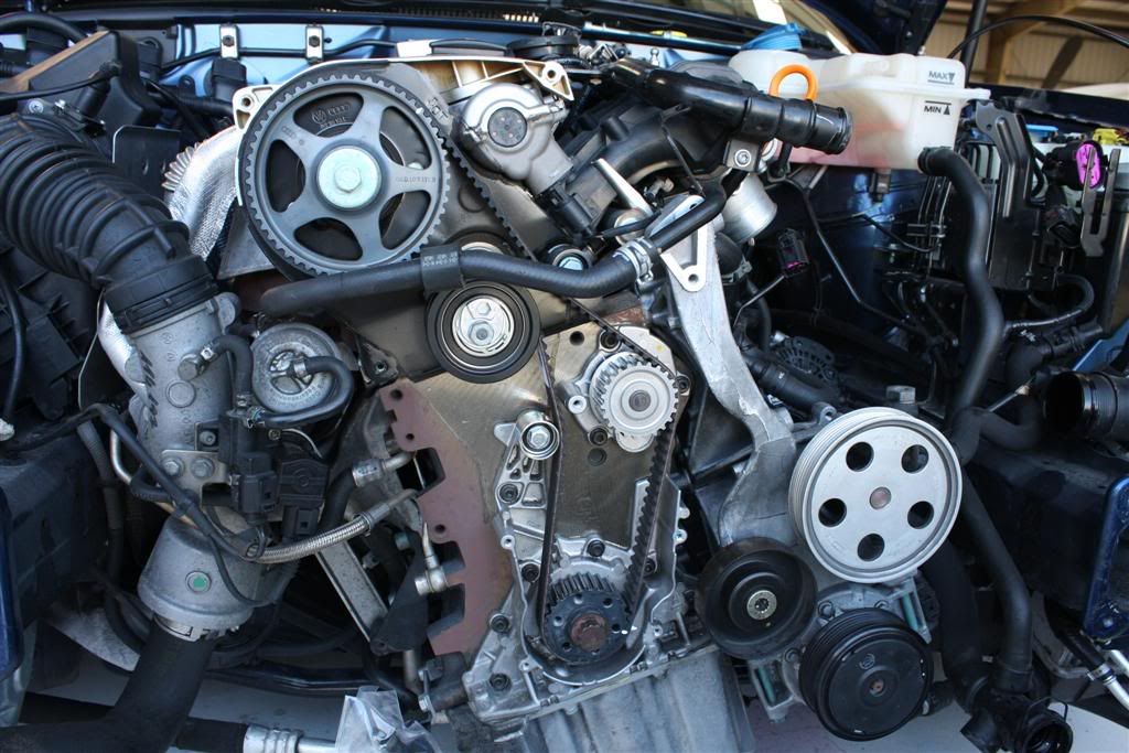


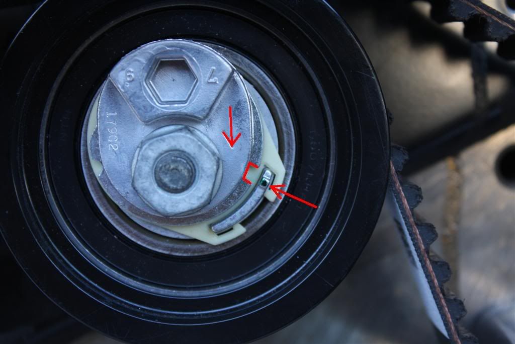
31) Hand tighten tensioner 13mm nut. Using 8mm Allen rotate clockwise until tab aligns with notch. Torque 13mm nut to 25nm.


32) The 4 engine mount bolts, 6 crank pulley bolts, and 2 washer bracket bolts are stretch bolts that should be replaced with new bolts every time. The 3 engine bracket bolts do not need to be replaced. 6mm crank pulley bolts are 10nm + ¼ turn. The 3 16mm engine bracket bolts are 45nm. The 2 18mm mount bolts are 60nm + ¼ turn. The 2 16mm mount bolts are 40nm + ¼ turn. 13mm washer bracket bolts are 20nm + ¼ turn. Wheel lug bolts are 110nm.


***TIPS TO PUTTING ON BELT:

The belt should always be put on the crankshaft gear last. Start by putting it on the tensioner, looping it over the top of the cam gear, and down past the waterpump and idlers, leaving the crankshaft gear for last.

The cam gear is at the top of the loop. The crankshaft gear is at the bottom of the loop. The tensioner is on the left side of the loop, so when the tensioner finally is tightened later on, it will take most of the slack from the left side of the loop, not the right. Before you can tighten the tensioner you must have the belt fully on the engine. When putting the belt on the gears, take all the slack out of the right side of the loop. The right side of the loop (the side with the water pump) needs to be extremely tight with all excess slack on the left side of the loop (the side with the tensioner).

If for some reason you do this and the belt is still a tooth off after 2 rotations, it's because the right side of the loop was not tight enough when putting it on the crankshaft gear. If you're having trouble pulling the belt down far enough on the right side to set it in the proper tooth, there is a way you can kind of "cheat" to get it on the proper tooth. To do this, pull down on the right side of the loop just as you did the first time (making sure the cam gear doesn't rotate when doing this, obviously). When doing this, you can turn the crankshaft gear counter-clockwise just a little. You are essentially bringing the tooth on the gear to the correct notch on the belt. Do not turn the crankshaft gear more than a tooth in the counter-clockwise direction as the cam gear is stationary up at the top of the loop. When you set the belt on the right tooth, turn the crankshaft back to where is was. At this point the belt should be tight on the right side, with the slack on the left side. Set the belt tensioner and rotate the crank 2 times to check again you have it on the correct tooth.
__________________


European Auto Gruppe aka EAG - Houston-based Euro club going on 11 years
« Last Edit: September 09, 2017, 10:07:48 pm by dazza »

05 | Tornado Red | DSG

Offline pudding

  • Global Moderator
  • Just look at my post count
  • *
  • Thank You
  • -Given: 2
  • -Receive: 690
  • Posts: 8354
Re: DIY: 2.0T FSI Timing Belt Replacement
« Reply #1 on: September 04, 2018, 06:54:03 pm »
Having done this to mine today, I thought I would add some additional notes and tips.

Parts list and torque specs at the bottom.

The car in Dazza's guide has the older 1 piece timing cover.  Cars with 2 piece covers have a slightly different procedure, otherwise the guide is accurate so I won't repeat what's already been said.

By far the most awkward part of this job is getting the engine mount support bracket in and out, otherwise it's a very simple job  :smiley:

In addition to the above, I replaced the water pump, so there will be some additional steps:

Before starting this job, I recommend checking measuring block 93 in VCDS with the engine idling. It should be in the 0 to -4KW range.

1 - After jacking the car up, removing the driver's side wheel, dropping the belly pan and lower arch liner - drain the coolant.   The easiest way is to pop a bucket under the lower radiator hose (just above the boost pipe) and let it all flow out.  Rather than messing with the quick release tab, which can be stubborn to come off, I pulled the clamp down. 

2 - Remove the two 16mm bolts that connect the dogbone to the gearbox.

3 - Remove the rubber boost hose.  I also removed the metal boost pipe as I wanted the work area as clear as possible, but you don't NEED to do that.

4 - Clear away everything from the upper work area, and I mean everything.  The timing belt covers are a pain to get off/on, so the less things in the way, the better.  This will ensure you don't lose patience and end up breaking the cover(s).


5 - Before removing the belt covers, I found it easier to loosen the mount bracket off to allow enough wriggle room to get the upper cover off.

6 -  Remove the bracket bolts as described above.  With the bracket loose, you can now move it far enough out of the way to remove the upper belt cover easily.
There is also this bolt that's tucked away out of sight where my finger is that has to come out.  I used a dentist mirror to see it.  When this bolt is out, remove the remaining lower cover bolts.  Remove the bracket by wiggling it and also the lower cover.......


7 -  ......I found the bracket would only come out if pulled up, forwards, and then towards the wing, whilst moving the lower cover around:


8 - Before removing the lower belt cover and crank pulley, time the engine as described, but also use the timing marks on the crank pulley - which he did not cover:


9 - Remove the crank pulley and lower belt cover.

10 -  With everything off, make additional marks on crank sprocket as shown.  This is needed for when you rotate the engine twice after fitting the belt to make sure the timing correct.


11- Remove the old belt, idler pullies, tensioning pulley and water pump.  Get that bucket under the block as loads of water will gush out when you pull the pump out.

12 - Now it's time to put the new stuff back on, which needless to say is the reverse of removal!   In the guide above, he mentions making sure the belt is really tight on the right hand side (under the water pump), but you don't need to worry about that too much.  Fit it as he describes as best you can.  When you tension the belt, it will pull tight.  Spin the motor twice and make sure the timing marks still align.

Fill the expansion tank with 50/50 G13 water mix and start the engine.  All should be good with no weird noises and idling smoothly.  If not, stop the engine immediately and recheck you work.  You will need to run the engine until the fans come on, whilst topping off the expansion tank.   Take it for a 20 min drive, check for leaks.  If you checked block 93 with VCDS at the start, check it again make sure the reading hasn't moved.   Check the coolant level the next day and top off if necessary.  All done  :happy2:

Parts list for belt + water pump change:

06F198119A - Repair kit (belt, idler pullies, tensioner etc)
06F121011 - Water pump with O ring
91143901 - qty 6 - Crank pulley bolts
90945002 - qty 3 - Bolt
90628303 - qty 2 - Bolt
90597005 - qty 1 - Bolt
91029602 - qty 1 - Bolt
90596906 - qty 1 - Bolt
10552402 - qty 2 - Bolt
2 bottles of G13 coolant


Torque specs:

16mm engine mount bracket to block - 45nm.
18mm engine mount - 60nm + 90 degrees.
16mm engine mount to body - 40nm + 90 degrees.
Crank pulley bolts - 20nm + 90 degrees.
Water pump - 15nm
Tensioner pulley nut - 25nm
Lower idler pulley - 35nm
Upper idler pulley - 25nm
« Last Edit: September 04, 2018, 06:55:44 pm by Pudding »


2007 ED30 | 2009 TDI 140 | 2016 BMW 330D

Offline doylebros

  • Just look at my post count
  • ******
  • Thank You
  • -Given: 44
  • -Receive: 309
  • Posts: 2775
Re: DIY: 2.0T FSI Timing Belt Replacement
« Reply #2 on: September 04, 2018, 08:08:56 pm »
Certainly a worthy update pudding,  one I can see others appreciating if they undertake the challenge of this DIY. :happy2:

Did you have any tips on refitting that bolt you identified with the dentist mirror or any tooling you found gave you the edge compared to what other DIYers may be missing?

Offline pudding

  • Global Moderator
  • Just look at my post count
  • *
  • Thank You
  • -Given: 2
  • -Receive: 690
  • Posts: 8354
Re: DIY: 2.0T FSI Timing Belt Replacement
« Reply #3 on: September 05, 2018, 01:54:49 pm »
I used a 3/8" sized torx socket with something sticky like blutack in the bolt head, which will stop it falling off  :happy2:

That bolt and one other were missing from my cover.  The tensioner was also not tightened correctly.  That's dealers for you!


2007 ED30 | 2009 TDI 140 | 2016 BMW 330D

Offline doylebros

  • Just look at my post count
  • ******
  • Thank You
  • -Given: 44
  • -Receive: 309
  • Posts: 2775
Re: DIY: 2.0T FSI Timing Belt Replacement
« Reply #4 on: September 05, 2018, 08:31:57 pm »
I used a 3/8" sized torx socket with something sticky like blutack in the bolt head, which will stop it falling off  :happy2:

That bolt and one other were missing from my cover.  The tensioner was also not tightened correctly.  That's dealers for you!
It's those types of pointers which are priceless and make a difficult job less difficult, for those working outside with limited tooling and prior knowledge and stops a lot of unnecessary  :thinking:

Offline pudding

  • Global Moderator
  • Just look at my post count
  • *
  • Thank You
  • -Given: 2
  • -Receive: 690
  • Posts: 8354
Re: DIY: 2.0T FSI Timing Belt Replacement
« Reply #5 on: September 07, 2018, 11:09:34 am »
Thanks mate.  That's why I post what I post, to pass on the knowledge.  I think more people should attempt this kind of work to save money and learn what makes their cars tick  :smiley:

Unlike the timing chain, no special tools are required to change a belt  :happy2:


2007 ED30 | 2009 TDI 140 | 2016 BMW 330D

Offline john_o

  • Just look at my post count
  • ******
  • Thank You
  • -Given: 136
  • -Receive: 108
  • Posts: 2946
    • My Car Blog
Re: DIY: 2.0T FSI Timing Belt Replacement
« Reply #6 on: September 08, 2018, 09:24:51 am »
comprehensive you two , well done for keeping this alive
Red ED35 5dr DSG
DEFI boost guage / RTech Stg1 Engine/DSG / PPMk7 front brakes
BLOG | BUILD

Offline Kayubra

  • Newbie
  • *
  • Thank You
  • -Given: 0
  • -Receive: 0
  • Posts: 2
Re: DIY: 2.0T FSI Timing Belt Replacement
« Reply #7 on: December 28, 2020, 10:37:23 am »
Great post.
Wanted to share my bit:
Upon changing the belt, tensioner, idlers, and water pump a misfire and rough idle were present. (triggering EPC light)
Happens that by raising and lowering the engine, the hose that brings vacuum to the brake booster got cracked and disconnected. At 259K km, it was brittle and split.   Here's a picture in case anyone runs into the same problem.
https://live.staticflickr.com/65535/50770436637_c6a6b55ebc_m.jpg
https://live.staticflickr.com/65535/50769571863_731d5732fe_m.jpg


Offline MartinNorhave

  • Just Arrived
  • **
  • Thank You
  • -Given: 0
  • -Receive: 0
  • Posts: 13
Re: DIY: 2.0T FSI Timing Belt Replacement
« Reply #8 on: October 21, 2024, 09:43:13 pm »
Having done this to mine today, I thought I would add some additional notes and tips.

Parts list and torque specs at the bottom.

The car in Dazza's guide has the older 1 piece timing cover.  Cars with 2 piece covers have a slightly different procedure, otherwise the guide is accurate so I won't repeat what's already been said.

By far the most awkward part of this job is getting the engine mount support bracket in and out, otherwise it's a very simple job  :smiley:

In addition to the above, I replaced the water pump, so there will be some additional steps:

Before starting this job, I recommend checking measuring block 93 in VCDS with the engine idling. It should be in the 0 to -4KW range.

1 - After jacking the car up, removing the driver's side wheel, dropping the belly pan and lower arch liner - drain the coolant.   The easiest way is to pop a bucket under the lower radiator hose (just above the boost pipe) and let it all flow out.  Rather than messing with the quick release tab, which can be stubborn to come off, I pulled the clamp down. 

2 - Remove the two 16mm bolts that connect the dogbone to the gearbox.

3 - Remove the rubber boost hose.  I also removed the metal boost pipe as I wanted the work area as clear as possible, but you don't NEED to do that.

4 - Clear away everything from the upper work area, and I mean everything.  The timing belt covers are a pain to get off/on, so the less things in the way, the better.  This will ensure you don't lose patience and end up breaking the cover(s).


5 - Before removing the belt covers, I found it easier to loosen the mount bracket off to allow enough wriggle room to get the upper cover off.

6 -  Remove the bracket bolts as described above.  With the bracket loose, you can now move it far enough out of the way to remove the upper belt cover easily.
There is also this bolt that's tucked away out of sight where my finger is that has to come out.  I used a dentist mirror to see it.  When this bolt is out, remove the remaining lower cover bolts.  Remove the bracket by wiggling it and also the lower cover.......


7 -  ......I found the bracket would only come out if pulled up, forwards, and then towards the wing, whilst moving the lower cover around:


8 - Before removing the lower belt cover and crank pulley, time the engine as described, but also use the timing marks on the crank pulley - which he did not cover:


9 - Remove the crank pulley and lower belt cover.

10 -  With everything off, make additional marks on crank sprocket as shown.  This is needed for when you rotate the engine twice after fitting the belt to make sure the timing correct.


11- Remove the old belt, idler pullies, tensioning pulley and water pump.  Get that bucket under the block as loads of water will gush out when you pull the pump out.

12 - Now it's time to put the new stuff back on, which needless to say is the reverse of removal!   In the guide above, he mentions making sure the belt is really tight on the right hand side (under the water pump), but you don't need to worry about that too much.  Fit it as he describes as best you can.  When you tension the belt, it will pull tight.  Spin the motor twice and make sure the timing marks still align.

Fill the expansion tank with 50/50 G13 water mix and start the engine.  All should be good with no weird noises and idling smoothly.  If not, stop the engine immediately and recheck you work.  You will need to run the engine until the fans come on, whilst topping off the expansion tank.   Take it for a 20 min drive, check for leaks.  If you checked block 93 with VCDS at the start, check it again make sure the reading hasn't moved.   Check the coolant level the next day and top off if necessary.  All done  :happy2:

Parts list for belt + water pump change:

06F198119A - Repair kit (belt, idler pullies, tensioner etc)
06F121011 - Water pump with O ring
91143901 - qty 6 - Crank pulley bolts
90945002 - qty 3 - Bolt
90628303 - qty 2 - Bolt
90597005 - qty 1 - Bolt
91029602 - qty 1 - Bolt
90596906 - qty 1 - Bolt
10552402 - qty 2 - Bolt
2 bottles of G13 coolant


Torque specs:

16mm engine mount bracket to block - 45nm.
18mm engine mount - 60nm + 90 degrees.
16mm engine mount to body - 40nm + 90 degrees.
Crank pulley bolts - 20nm + 90 degrees.
Water pump - 15nm
Tensioner pulley nut - 25nm
Lower idler pulley - 35nm
Upper idler pulley - 25nm

When I look at block 93 my phase position is at -6. You say that we should check that it is within range. But not what we should do if it is outside